|
|
Phototube Test
|
|
This page describes the status of the test of MAPMT's to be used
for the MiniPlug calorimeter. We are planing to use 16-channel MAPMT's
manufactured by
Hamamatsu
(
H6568-10/R5900 M16).
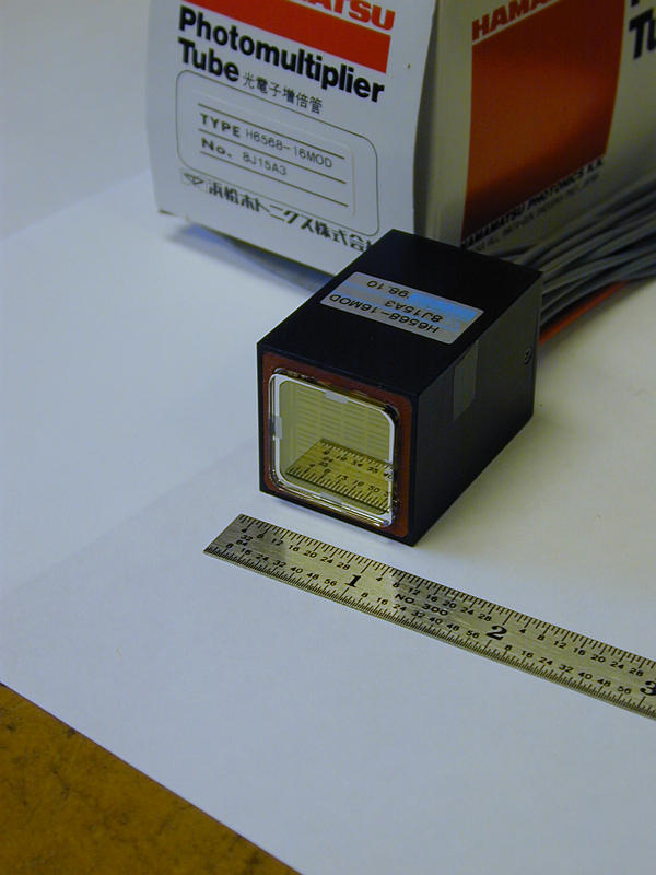
Two types of MAPMTs are provided by the manufacturer:
one with a 2 mm thick window and a 4 MOhm voltage divider (H6568-16 MOD),
and another with a 1mm thick window and 1 MOhm voltage divider (H6568-16 REV).
The characteristics of H6568-10/R5900 M16 MAPMT's
specified for the MiniPlug calorimeter are shown in
here.
| H6568-16 MOD | H6568-16 REV |
| 2mm thick window & 4Mohm voltage divider | 1mm thick window & 1Mohm voltage divider |
Since individual PMT's may have substantially different
characteristics
from those provided by the manufacturer, it is important to measure
all the PMT's we receive and verify that they conform to our requirements.
We have a setup which allows us to evaluate MAPMT's. The setup which we
used is shown in this figure.
You can find more details in
this document.
| No. | PMT Serial
Number |
Window
Thickness |
Resistor
Dividor |
High Voltage
(V) |
Relative Gain | Uniformity |
| 1 | 8J15A3 | 2mm | 4M | 740 | rel_8j15a3.ps | 1:2.4 |
| 2 | 8J10A1 | 2mm | 4M | 670 | rel_8j10a1.ps | 1:1.8 |
| 3 | 8J15A2 | 2mm | 4M | 800 | rel_8j15a2.ps | 1:2.3 |
| 4 | 9J09C8 | 2mm | 4M | 690 | rel_9j09c8.ps | 1:1.9 |
| 5 | 9J09C9 | 2mm | 4M | 690 | rel_9j09c9.ps | 1:2.5 |
| 6 | 9H24D1 | 2mm | 4M | 670 | rel_9h24d1.ps | 1:2.3 |
| 7 | 9H24D2 | 2mm | 4M | 650 | rel_9h24d2.ps | 1:1.7 |
| 8 | 9H30D2 | 2mm | 4M | 680 | rel_9h30d2.ps | 1:3.0 |
| 9 | 9H30D6 | 2mm | 4M | 730 | rel_9h30d6.ps | 1:1.9 |
| 10 | 9J06R2 | 2mm | 4M | 700 | rel_9j06r2.ps | 1:2.2 |
| 11 | 9J06R4 | 2mm | 4M | 710 | rel_9j06r4.ps | 1:2.1 |
| 12 | 9J06R9 | 2mm | 4M | 740 | rel_9j06r9.ps | 1:1.9 |
| 13 | 9J06RA | 2mm | 4M | 720 | rel_9j06ra.ps | 1:1.6 |
| 14 | 9J16R2 | 2mm | 4M | 710 | rel_9j16r2.ps | 1:2.1 |
| 15 | 9J16R3 | 2mm | 4M | 780 | rel_9j16r3.ps | 1:2.7 |
| 16 | 9J16R4 | 2mm | 4M | 750 | rel_9j16r4.ps | 1:2.4 |
| 17 | 9K08C6 | 2mm | 4M | 650 | rel_9k08c6.ps | 1:2.3 |
| 18 | 9K08C8 | 2mm | 4M | 660 | rel_9k08c8.ps | 1:2.5 |
| 19 | 9K08C9 | 2mm | 4M | 670 | rel_9k08c9.ps | 1:2.6 |
| 20 | 9K15Q2 | 2mm | 4M | 670 | rel_9k15q2.ps | 1:2.1 |
| 21 | 9K15Q5 | 2mm | 4M | 750 | rel_9k15q5.ps | 1:2.8 |
| 22 | 2KB101 | 2mm | 4M | 710 | rel_2kb101.ps | 1:1.7 |
| 23 | 2KB171 | 2mm | 4M | 710 | rel_2kb171.ps | 1:2.0 |
| 24 | 2KB231 | 2mm | 4M | 630 | rel_2kb231.ps | 1:1.9 |
| 25 | 2KC032 | 1mm | 1M | 660 | rel_2kc032.ps | 1:1.5 |
| 26 | 2KC092 | 1mm | 1M | 660 | rel_2kc092.ps | 1:2.1 |
| 27 | 2KC294 | 1mm | 1M | 740 | rel_2kc294.ps | 1:2.8 |
| 28 | 2KC295 | 1mm | 1M | 690 | rel_2kc295.ps | 1:2.8 |
| 29 | 2KC297 | 1mm | 1M | 670 | rel_2kc297.ps | 1:1.8 |
| 30 | 2KC299 | 1mm | 1M | 670 | rel_2kc299.ps | 1:1.8 |
| 31 | 2KC303 | 1mm | 1M | 680 | rel_2kc303.ps | 1:1.8 |
| 32 | 2KD051 | 1mm | 1M | 670 | rel_2kd051.ps | 1:1.7 |
| 33 | 2KD052 | 1mm | 1M | 680 | rel_2kd052.ps | 1:1.8 |
| 34 | 2KC281 | 1mm | 1M | 710 | rel_2kc281.ps | 1:1.8 |
| 35 | 2KC282 | 1mm | 1M | 650 | rel_2kc282.ps | 1:1.9 |
| 36 | 2KC283 | 1mm | 1M | 670 | rel_2kc283.ps | 1:1.7 |
| 37 | 2KC284 | 1mm | 1M | 730 | rel_2kc284.ps | 1:2.0 |
| 38 | 2KC286 | 1mm | 1M | 700 | rel_2kc286.ps | 1:2.4 |
| 39 | 2KC291 | 1mm | 1M | 720 | rel_2kc291.ps | 1:2.0 |
| 40 | 2KC292 | 1mm | 1M | 710 | rel_2kc292.ps | 1:1.6 |
| 41 | 2KC293 | 1mm | 1M | 660 | rel_2kc293.ps | 1:1.8 |
| 42 | 2KC296 | 1mm | 1M | 720 | rel_2kc296.ps | 1:2.0 |
| 43 | 2KC298 | 1mm | 1M | Broken!! | ||
| 44 | 2KC301 | 1mm | 1M | 730 | rel_2kc301.ps | 1:2.3 |
| 45 | 2KC302 | 1mm | 1M | 700 | rel_2kc302.ps | 1:2.4 |
Note 1), The High Voltages values shown in the above table are
the HV values at which that PMT shows approximately the same output as
the other PMT's.
Note 2), Figures in the "Relative Gain" column show (top) relative
gains of 16 MAPMT channels, (middle) differences between our measurements
and numbers from Hamamatsu, (bottom left) relative gains of 6 grouped channels.
( Channel-A : Channel-1,2,3, Channel-B : Channel-5,6,7,
Channel-C : Channel-9,10,11, Channel-D : Channel-13,14,15,
Channel-E : Channel-16) and (bottom right) differences between relative
gains of 6 grouped channels and expectations from measurements of 16 individual
channels.
Note 3), The uniformity is defined as the ratio of the minimum
to the maximum relative gains. Distributions for the uniformity are shown
here.